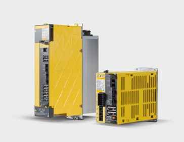
Fanuc System 9 Series
Fanuc 9 CNC Control Specifications.
The FANUC SYSTEM 9 series are high-performance CNC's for sophisticated machining in the aircraft, automobile, and other industries, They are suitable for multiple axis control (simultaneous max. 15-axis control) multi head control, synchronised operation, operation check system and hybrid servo control, while other functions provide large-sized machine tool control, high precision machining and complicated control. With high-speed microprocessors, LSIs and large capacity of memory, FANUC 9 series can provide full software functions for many applications and construct a high-performance/cost ratio CNC system. FANUC SYSTEM 9 series use the FANUC DC SERVO MOTOR series, which is the world's most widely used servo motor, resulting in high speed, power and stable machining, adding the fine positioning control with software.
Number of Axes Controlled at a time (up to 15 axes) (option)
The number of axes controlled at any time can be expanded up to a maximum of 15 axes. Maximum 15 axes (Number of motors) can be controlled including synchronously operated axes and parallel controlled axes.15 axes can be controlled at a time by manual feed also.

Synchronous Operation Control (option)
This function moves two movable bodies in the same manner as much as possible and is used to drive a gantry by two motors, for example
User Macro Function (option)
Your own program for special canned cycle, pattern function and etc. can be incorporated in FANUC 9 SYSTEM Series. In other words, you can extend the functions of Fanuc System 9 Series by making software yourself. This is just one good example showing the flexibility of Fanuc System 9 series.
Functions below can be used in user macro
- a) The following operators and functions can be used in the operation: + (addition), - (subtraction), x (product), % (quotent), OR (logical add), XOR (exclusive logical add), AND (logical product), SIN (sine), COS (cosine), Tan (tangent), ATAN (arc tangent), SQRT (square root), ABS (absolute value), BIN (conversion from BCD to binary), BCD (conversion from binary to BCD)
- b) Conditional or unconditional jump
- c) Repeat
- d) Modal macro call at each positioning
- e) DI 16 points can be read as variable, DO 16 points can be output
Part Program Storage and Editing Using Large Capacity Bubble Memory (option) Part program storage and editing function capable of storing and editing correction, deletion, and insertion of up to 900 meters tape. One the part program had been stored in memory, the machining can be repeated without the NC tape, Since the part program stored can be displayed on the CRT part program can be corrected easily and error can be eliminated. Fanuc 9" CRT is provided as standard. such as the TR9DK1A Model.
Three Dimensional tool Offset
In machining a curved surface, offset by an offset value set in a 3-dimensional direction is provided, The offset direction is given as a vector with I,J,K together with X,Y,Z by a programmed command.
Coordinate System Rotation (option)
Rotation of a programmed shape is possible.
Hybrid Servo Control (option)
semi closed loop and closed loop are mixed substantially to raise the servo gain. Up to 15 axes are possible. This function drives a large machine tool rapidly.
Operation Check System (option)
Operation check system can be composed which advances motion whilst collating results of duplex motion in order to prevent a work piece from been cut erroneously
NC/TC Function (option)
Furnishing with NC/TC function, only one controller of FS9 can execute the function which two controller (NC and TC) had executed, A machining system suited to a profile can be selected for efficient die shaping
- Tracing for 3-dimensional machining requiring difficult tape preparation
- NC machining for high-precision 2 and 3-dimensional shaping
- Combined use of NC and tracing for contours with convex and concave bottom surfaces or complex grooves, which are difficult to machine only with a single function of NC or tracing
- Machine Center
- Many kinds of canned cycles
- Variety of pattern functions simplifying programming for positioning
- Tool length measuring
- Handle interruption during automatic operation
- 3-Dimensional cutter radius compensation
- Work coordinate setting, Machine coordintae setting, and Local coordinate setting
- Single direction positioning
- Fanuc alarm message from outside and message for operator can be input and displayed on CRT
- Punch Press
- Variety of patterns
- Nibbling of any shape
- Compensation of bending allowance
- Automatic repositioning
- Turrent position offset
- Control of turret rotation
- Multi shapes from one metal sheet
- Tube Plate and Drum Drilling Machine
- Canned cycles for drilling
- User macro function
- High-speed positioning
- Error detector in positioning
- Compensation for work set error
- Variety of patterns
- Large Size Planomiller
- Feed function for any angle
- Synchronous operation and synchronization error compensation for gantry
- Special tool position offset
- 3 manual pulse generators
- Flame Cutter
- Torch head rotation
- Kurf with compensation
- Closed curve, smoothly linked line cutting
- Marking offset
- Reverse direction control
- ESSI format
- Digitizer
- 3-dimensional tool offset
- Coordinate system setting
- Data processing for rough machining
- Area designation
- Scaling
- Coordinate system rotation
Furthermore, Fanuc System 9 series can be applied to roll lathes, grinding machines, drilling machines, P.C.B. drilling machines, welding machines, thread grinding machines, drafters, etc.
Specification
Standard
Controlled Axes: 3 axes (maximum 15 by option)
Simultaneously Controllable Axes: Positioning, Linear Interpolation, Manual Feed; all axes.
Circulation interpolation; 2 axes
Tape Code: EIA RS-244-A or ISO 840 (automatic switching)
Decimal Point Programming
Input Unit 10 Times
Program Number
Rapid Traverse Override: Fo, 25, 50, 100% (Fo: Set by parameter)
Feed Override: Override 0~200%(10% step)
Dry Run
Automatic Acceleration/Deceleration
Interpolation: Positioning, Linear Interpolation, and Multiple Quadrant Circular Interpolation
Dwell: G04
Alteration of offset value, setting data, and program by parameter: G10
Reference Point Return Cleck: G27
Automatic Reference Point Return: G28, G29
Second, Third, Forth Reference Point Return: G30
Tool Length Offset: G49, G43, G44
Tool Offset: G45~G48
Programming by Machine Coordinate System: G53
Selection of Work Coordinate System: G54~G59
Exact Stop Check: G09
Exact Stop Check Mode: G61
Cutting Mode: G64
Absolute/Incremental Command: G90/G91
Programming of Work Zero Point: G92
Setting of Local Coordinate System: G52
S Functions: 4 Digits
T Functions: 4 Digits
M Functions: 2 Digits
Parity Check of BCD Output
Manual Feed: Jog, Manual Rapid, Incremental
Manual Numerical Value Command
Manual Reference Point Return
Machine Lock
Z axis Command Cancel
Feed Hold
Single Block
Optional Black Skip
Mirror Image
Interlock
Auxilary Functions Lock
Servo Off
MDI and CRT Unit
Tape Reader Without Reels: 300 ch/sec (60Hz), 250 ch/sec(50Hz)
Photo Electric (light emitting diodes)
Tape Tumble Box; Tape Length 30 m
Sequence Number Search
Backlash Compensation: Maximum 255u, 0.0255 inch
Stroke Check
Over Travel Check
Stored Pitch-Error Compensation
Feedback: Resolver
Self Diagnosis
Power Supply: AC 200V/220V, 50/60 Hz, 3 Phase
Option
Part Program Storage, Editing and Sub Program: Tape Capacity 300m, 600m, 900m
4~8 Axes Control
9~15 Axes Control
Parallel Axis Control
Tape Reader With Reels: 300 ch/sec (60Hz), 250 ch/sec(50Hz)
Photo Electric (light emitting diodes)
Reel Capacity: 150 m
Remote-type MDI and CRT Unit
Manual Pulse Generator 1st
Manual Pulse Generator 2nd, 3rd
Spindle Speed Analog Output
F-1 Digit Feed rate
User Macro A
User Macro B
Helical interpolation: G02, G03
Inch/Metric Conversion: G20, G21
Stored Stroke Limit: G22, G23
Thread Cutting: G33
Cutter Radius Compensation C: G40, G41, G42
Single Direction Positioning: G60
Canned Cycle: G73, G74, G76, G80~G89, G98, G99
External Cycle Function: G80, G81
Feed per minute, Feed per revolution: G94, G95
Scaling: G51, G50
Rotation of Coordinate System: G68, G69
Skip Function: G31
Mirror Image
B function
Three Dimensional Tool Offset
Tool Length Measurement
Automatic Corner Override
External Deceleration
External Tool Compensation
External Program Number Search
External Work Coordinate Shift
Machine Coordinate System Compensation
External Alarm Message
External Operator Message
Restart
FACIT Interface
ASR Interface
RS232C Serial Data Interface
Remote Type Position Display
Door Interlock
NTC Interface
Hybrid Servo Control
Operation Check System A: Positioning
Operation Check System B: Cutting
Synchronous Operation Control
Built in type Programmable Controller
Position Coder
Feedback Adapter: For Inductosyn or Optical Scale
Inductosyn Pre-Amplifier
Fanuc Servo Velocity Control Unit
Servo Locker A
Servo Locker B
Floppy Disk Unit
Input Transformer
Fanuc Servo Transformer
Popular related spare parts A81L-0001-0157, A03B-0801-C449, A03B-0801-C421, A03B-0801-C136, A81L-0001-0122
Download the Fanuc System 9 Series Datasheet


